
Views: 0 Author: Site Editor Publish Time: 2026-11-13 Origin: Site


High-efficiency switching topologies, particularly Class D designs, manage significant current and voltage. They dissipate minimal heat during normal use. However, this impressive efficiency creates a hidden vulnerability. The same components can experience rapid, catastrophic failure during unexpected load faults. System integrators and engineers face a distinct challenge. When you evaluate a switching power amplifier, the internal protection architecture matters most. It serves as the primary differentiator between reliable long-term operation and costly equipment loss. Relying on basic power output specifications often leads to unexpected field failures.
This guide breaks down critical internal safeguards. You will discover how different electronic intervention methods directly impact audio performance. We also outline the exact criteria required to evaluate modern hardware. You will learn how to specify the right amplifier for mission-critical audio or demanding industrial applications.
Risk Mitigation: Robust power amplifier protection circuits prevent localized faults (like shorted cables) from cascading into total system failure or secondary speaker damage.
Intervention Variances: Not all protection is equal; evaluators must weigh hard-shutdown mechanisms against foldback limiting that keeps systems live during transient faults.
Real-World Load Handling: Superior protection designs account for reactive loads and complex impedance curves to prevent "false tripping" during standard operation.
Evaluation Focus: Specifying the right switching power amplifier requires analyzing how the thermal and current protection interacts with the intended operating environment and load threshold.
Modern switching topologies utilize fast-acting MOSFETs or advanced GaN transistors. These components switch at incredibly high frequencies to deliver power efficiently. A sudden load anomaly can easily exceed internal component tolerances in mere microseconds. Without a dedicated power amplifier protection circuit, these delicate silicon structures fail instantly.
The consequences of inadequate protection extend far beyond a blown external fuse. You face three distinct risks when evaluating hardware safeguards.
Hardware Loss: Extreme faults destroy the delicate output stage. You often face complete motherboard replacement rather than a simple bench repair.
Collateral Damage: When output transistors fail, they often leak raw DC voltage. This raw energy travels down the wire and melts the voice coils inside connected transducers and expensive speakers.
Operational Downtime: Unplanned outages destroy user confidence. In a live touring scenario, an unplanned outage stops the show completely. This destroys audience trust and incurs immediate financial penalties. In commercial environments, like stadium public address networks, failure represents a severe compliance liability.
What defines a successful protection suite? It acts invisibly during normal operation. You should never hear it working. However, it must intervene predictably during a verifiable fault. It also needs to recover smoothly once you resolve the underlying electrical issue.
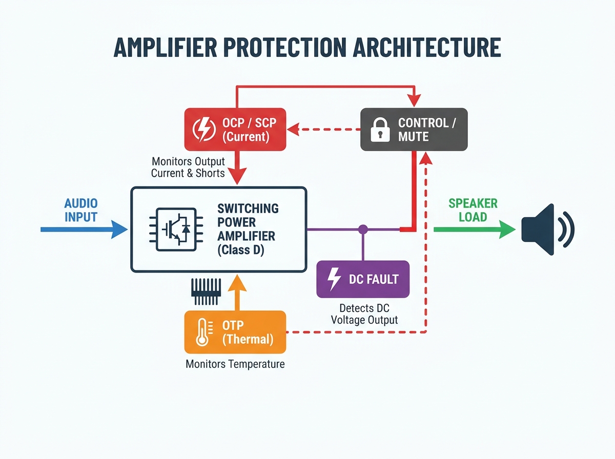
Modern audio designs rely on layered safety nets. Each layer handles a specific electrical anomaly. Let us explore the core mechanisms you will encounter.
The system monitors output current continuously. It ensures internal operation remains within the safe operating area (SOA) of the transistors. Proper amplifier overload protection manages scenarios where impedance drops too low. For example, running too many speakers in parallel stresses the power supply significantly.
Evaluation Note: You should look for cycle-by-cycle current limiting. This modern approach reacts faster than traditional averaging sensors. It keeps the music playing while pulling the current draw back to safe limits dynamically.
A dead short across speaker terminals presents an immediate threat. Dedicated amplifier short circuit protection serves as an aggressive subset of overcurrent monitoring. It detects a near-zero ohm load instantly.
Evaluation Note: The circuit must act in nanoseconds. It needs to mute the drive signal entirely before the next switching cycle destroys the output transistors. Delay means complete component failure.
High power output eventually generates heat. Effective amplifier thermal protection monitors both the external heatsink and the internal silicon junction temperatures.
Evaluation Note: Seek out multi-stage thermal management. Good designs trigger cooling fans first. If heat continues to rise, they reduce system gain slightly. Shutting down completely should only happen as a last resort. Avoid basic binary on/off thermal switches.
Output transistors occasionally fail. When they do, they can dump continuous DC voltage directly into the speaker line. DC current does not alternate; it pushes the speaker cone entirely outward or inward and holds it there. The voice coil cannot cool itself through normal pistonic motion. DC fault protection detects this steady voltage immediately. It physically disconnects the load to save your speaker cones from melting.
Engineers must balance absolute safety against show continuity. When a fault occurs, the amplifier must decide how to react. These hardware reactions generally fall into two distinct intervention categories.
Table: Comparison of Amplifier Intervention Methods
Intervention Type | Operational Mechanism | Primary Advantages | Notable Drawbacks |
|---|---|---|---|
Hard Mute / Shutdown | The amplifier completely latches off upon detecting a severe fault. | Maximizes absolute safety. Prevents any further electrical damage immediately. | Guarantees operational downtime. Often requires manual power cycling or a long timeout reset. |
Current Limiting / Foldback | Dynamically reduces output current or voltage gain to run safely. | Keeps the event running. Crucial for live audio or continuous industrial processes. | Introduces heavy compression or audible distortion during the fault event. |
Protection circuits carry an inherent implementation risk. Poorly designed networks can interfere with the audio signal even when they sit dormant. They might add parasitic capacitance or subtle non-linearities to your sound profile.
High-end switching power amplifier designs avoid this problem entirely. They use isolated sensing techniques, like optical sensors or dedicated current transformers. This isolation preserves signal integrity while keeping the safety net ready.
Theoretical lab tests often fail to predict real-world audio challenges. You must consider how protection topologies behave under actual touring or integration conditions.
Speakers do not behave like static resistors. They represent highly reactive loads with massive inductive and capacitive swings. The phase angle between voltage and current shifts dramatically depending on the frequency being reproduced. When a massive bass transient hits, the amplifier must deliver high current while the voltage sits at a minimum.
A protection circuit calibrated solely for a static resistive load causes headaches. It remains highly prone to "false tripping" during heavy, low-frequency transient hits. Superior designs model complex impedance curves to differentiate between a heavy bass drop and a true short circuit.
Temperature monitoring involves physical delays. Surface-mounted thermistors experience a noticeable time lag. The actual silicon overheats much faster than the surrounding heatsink warms up. You must verify how the amplifier handles thermal inertia. Does it calculate and model actual junction temperatures? If it only reads the ambient heatsink temperature, it might react too late to save the silicon.
AC mains power fluctuates constantly in industrial settings or outdoor touring environments. Standard amplifiers might reboot if the wall voltage drops slightly. Sophisticated Undervoltage Protection (UVP) circuits ride through these minor sags. They keep the system operational without unnecessarily rebooting the amplifier during a temporary power dip.
How do you narrow down your hardware choices? Use a systematic approach to match the amplifier's capabilities with your environmental risks. Follow these distinct evaluation steps.
Define the Load Profile: Look beyond the nominal 8-ohm or 4-ohm ratings. Match the amplifier's current delivery capabilities to the lowest impedance dip of your intended speaker load. This ensures the protection triggers only during actual faults.
Review the Recovery Protocol: Determine what happens after a fault clears. Verify whether the hardware features auto-recovery. Remote installations demand systems that reset themselves after a thermal event. Manual resets require costly truck rolls.
Analyze the Spec Sheet for Transparency: Trustworthy manufacturers publish precise data regarding their thresholds. You should look for clear metrics like "Thermal mute at 90°C, auto-reset at 75°C." Avoid brands relying on vague marketing claims of "bulletproof protection."
Request Real-World Testing Data: Do not just trust the brochure. Ask vendors for actual burst-power and short-circuit recovery test results. Ask for documentation showing how the amplifier handles a dead short applied precisely at full power output. This data validates their claims under genuine stress conditions.
Evaluating audio hardware requires a deep look at failure-prevention architecture. The internal safeguards dictate the total lifecycle reliability of your investment.
Never prioritize raw wattage over system stability. Massive power means nothing if the unit destroys itself during a minor fault.
An amplifier featuring sophisticated, multi-stage intervention will consistently outlast a higher-powered alternative with rudimentary safety switches.
Focus on auto-recovery features to minimize system downtime and reduce maintenance labor in remote commercial installations.
Review your project requirements carefully today. Compare your specific load demands against the protection topologies discussed in this guide. This focused approach will help you narrow down your shortlist and specify truly reliable hardware for your next installation.
A: In modern, well-engineered designs, they do not. Advanced protection circuits operate entirely outside the primary signal path. They utilize isolated current transformers or optical sensors. These components monitor the system without adding parasitic capacitance. Therefore, they do not impact THD or frequency response until a specific fault threshold is actually crossed.
A: Overload protection handles conditions where overall impedance drops too low, like running too many speakers in parallel. It usually engages current limiting to keep things running safely. Short circuit protection delivers an instantaneous response to a dead short (0 ohms). It usually results in an immediate hard mute to save the delicate output stage.
A: Most commercial and high-end units feature auto-recovery capabilities. Once the internal temperature drops below a predefined safe hysteresis threshold, the system re-engages. The amplifier will automatically restore the audio output without requiring manual intervention or physical power cycling.
A: This behavior usually indicates a mismatch between the amplifier's current capability and the speaker's electrical demand. The speaker load impedance likely dips too low at specific bass frequencies. High-demand transients trigger the overcurrent protection. The system runs fine at low volumes because the overall current draw remains well within safe limits.


